This page is part of a series on Annax flipdot modules. The previous part covers a high-level overview of the control board and the entire display. The current part (this page) discusses parts of the control board in greater detail. I'll assume you've read at least the flipdot-panel and control PCB (BZS3) sections.
(At a later time, I will extend this part of the series by some details about the memory mapping and some leftover chips. Stay tuned!)
In this article:
(See the previous part for a high-level overview of the major components)
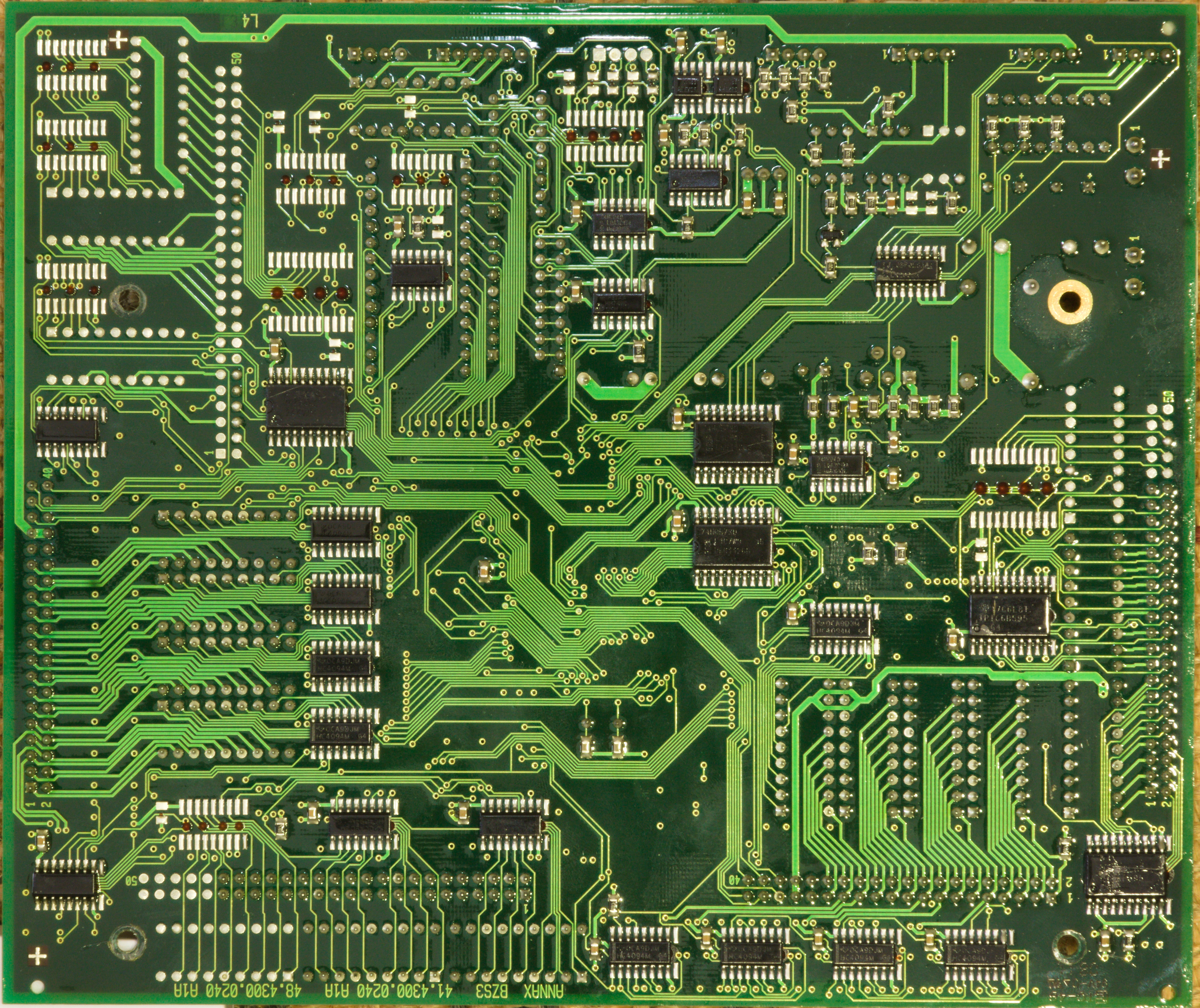
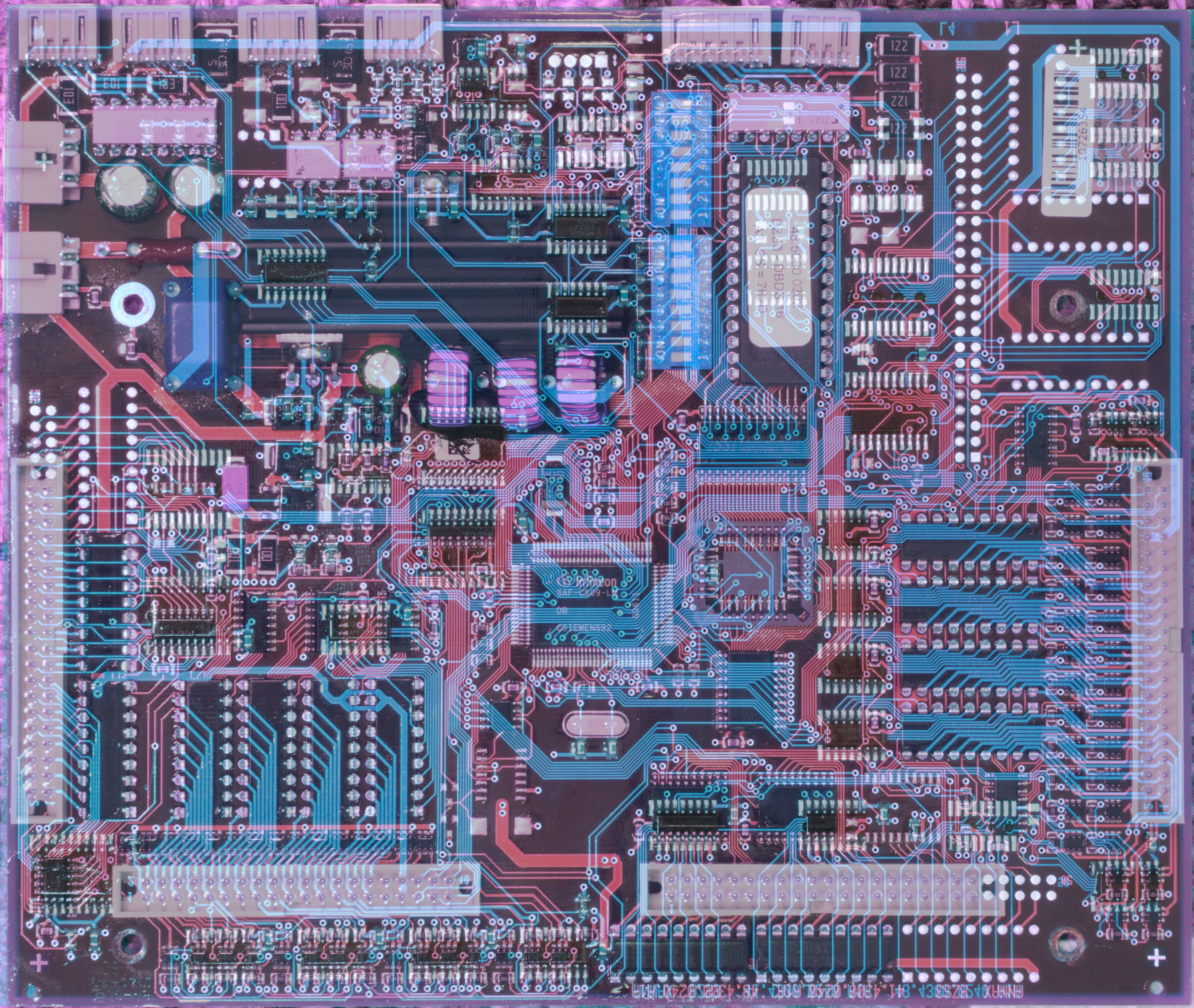
One thing that helps a lot with reverse engineering is that while it is a 4-layer board, the two inner layers are exclusively used as power planes. This means you can follow most signals simply by looking at a photo. Only occassionally does a signal disappear under a chip into nowhere and you actually need a continuity tester – which is also relatively easy since the vias are not covered (only a thin layer of conformal coating which you can easily poke through). Aligning and overlaying photos of front and back helps here, too.
Some vias seem to go to nowhere, which means they either go to the ground plane or the 5V plane. The ones on the driver ICs go to 24V, which is also on an inner plane (probably cuts through the 5V plane). As the pins of the voltage regulator are easily reachable (in case of GND, even their cooling tabs will do) these signals are extremely easy to detect with the multimeter.
So you're building a universal control board for variable display sizes, and your text rendering code needs to know how many pixels it can use. One obvious way would be to store the display size in an EEPROM (which does exist on the board).
Or you don't, and instead you let the board check how many display panels are installed and how many pixels they have.
The coil of any pixel has quite low DC resistance, 80 ohm for this display, which at 24 V results in 300 mA of current. When powering up the display, you simply go through all pixels of a one row and one column, put a short pulse on them, and measure current consumption. If you observe significant current, you know there's a pixel at the position you just tested. If there's almost no current, there is no pixel (or a burnt coil) and you just found out one dimension (X or Y) of one panel. Repeat this process for all of the (up to) 6 panels, and you know the size (and layout) of your display :)
This also means if a coil in the first row, or the first column of any panel, is broken, the firmware assumes it found the last pixel, ignores the rest of the panel, and continues at the next panel. You'll get a visible gap in the middle of the display and probably a narrower font to compensate for the "narrow" display, but no missing characters.
Of course, this doesn't cover the more common case of the coil itself being operational, but the mechanical dot being worn out. (I'm not sure if it would even be possible to reliably detect stuck pixels (certainly not with typical late-1990ies hardware). Nowadays, it is possible to detect lost steps of a stepper motor by precisely monitoring back EMF and current consumption, but the back EMF of a small plastic platelet with a tiny magnet is probably indistinguishable from noise.)
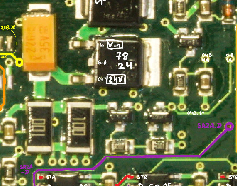
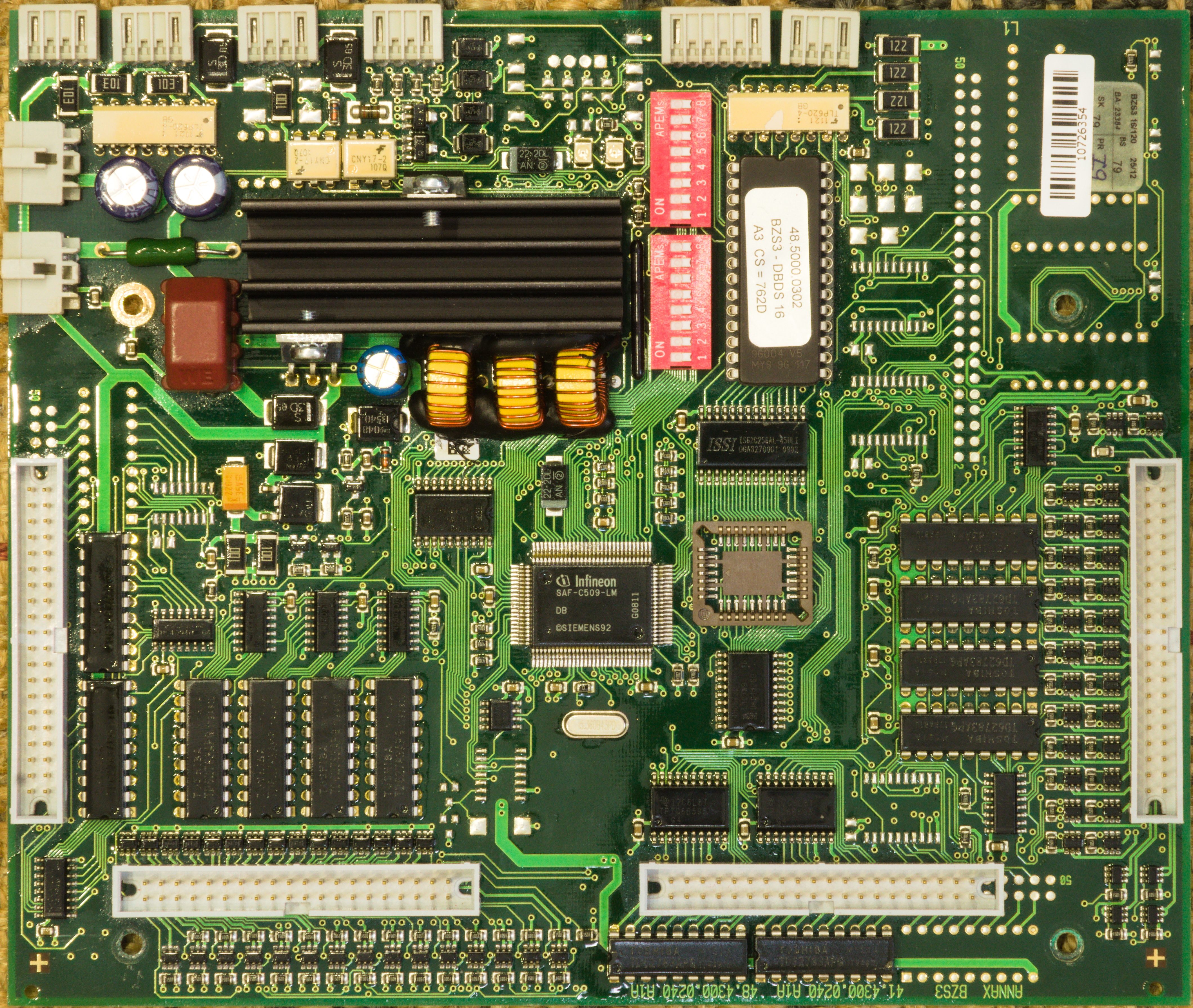
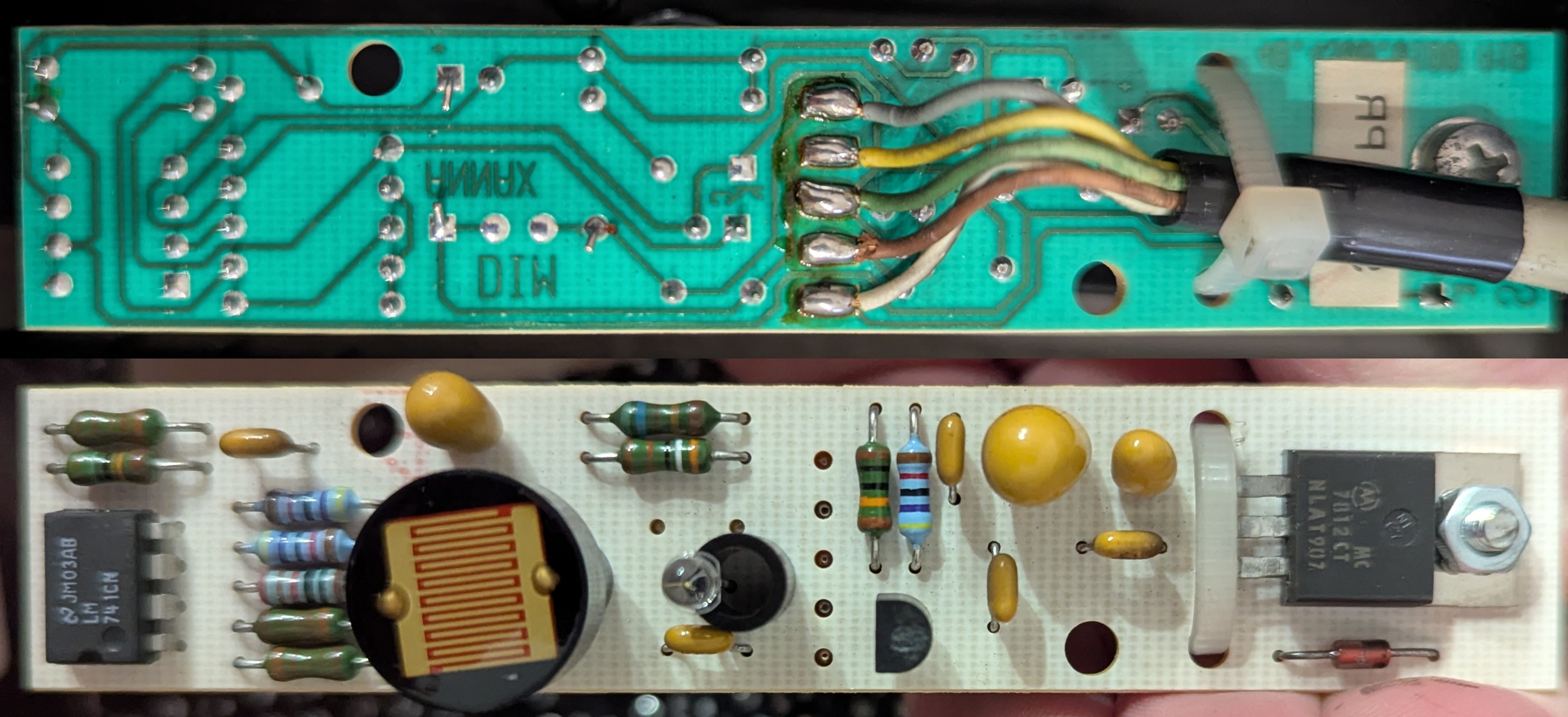
To actually measure the current, the typical approach is to use a shunt, i.e. a low-resistance (few ohms usually) resistor, and place it in series with the load to be measured. Any current drawn from the 24 V rail causes a (small) voltage drop across the 5 ohm shunt (in the photo: two 10 ohm resistors in parallel), proportional to the current. You could then use an ADC or an op-amp based comparator circuit or something like that, and define a suitable threshold for "there's probably a coil here".
An op-amp obviously costs money. The C509 MCU actually has an ADC that is not otherwise used (and therefore doesn't cost money), but you'd have to protect its input from e.g. voltage spikes (remember, we're measuring a coil!). Also, the resistor is on the high side, so you're not trying to distinguish between zero and a few hundred millivolts, but between 24 V and around 23 V, which is possible with the 10-bit ADC (if you bring the signal down to 5 V first, at least), but not at a great resolution.
Instead of spending money on components to protect an ADC that is kind of imprecise anyway, you can buy a very cheap component that has one sufficiently precise parameter: a transistor.
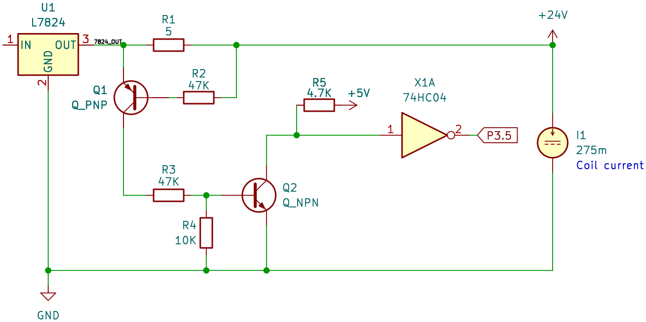
The idea behind this circuit is quite simple: A PNP transistor starts conducting as soon as there is an emitter-base current, which normally (If the base of a PNP transistor is a lot more positive than the emitter, it will break down and start conducting anyway. I encountered this on the ambient light sensor board (a later part of this series), with an NPN transistor, for which this happens if its base is a lot more negative than the emitter.) happens as soon as the base is at least ~ 0.7 V more negative than the emitter.
The point at which this happens can be calculated (or you can throw it in the simulator, KiCad schematic). Hence, in this setup, if more than approximately 150 mA are drawn, the voltage drop over the shunt is enough to make the PNP transistor turn on. This causes the NPN to also turn on, which pulls down the input of the inverter, and causes port pin P3.5 to go high.
As we've already seen above, single flipdot coil with about 80 ohm DC resistance draws 300 mA, so this circuit will quite reliably detect a flipping dot (or at least a coil drawing current, you won't figure out if the colored plate actually flipped), which you can then use to detect module sizes as described above.
In the photo above, you might have noticed a third transistor (to the right of the 7824) in addition to the two that were used for the 24V current sensing. The surrounding circuit looks like this:
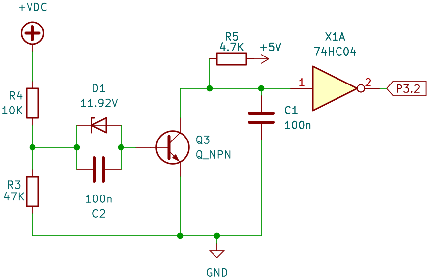
This is a brownout detector! It checks if the input voltage is above some threshold. This is done as follows: a sufficiently high input voltage, and therefore also a sufficiently high voltage at the center point of the 10K/47K voltage divider, causes the zener diode to break down, resulting in a base current and thus the transistor turns on. This pulls down the inverter input and port pin P3.2 is high. If the input voltage is too low, the zener turns off, there no longer is any base current (Ideally there would have been a pulldown resistor at the base so that it quickly reaches a defined voltage if the zener is turning off, instead of floating at an undefined potential and being sensitive to EMI. All transistors on the board have a pulldown resistor at the base ... except for this one. Leakage currents may keep the circuit somewhat stable in practice.), and the transistor turns off, resulting in P3.2 being low.
The zener diode has a breakdown voltage of 12 V (measured: 11.92 V). The voltage divider on the left causes this to happen at a V_in of 14.5 V. The transistor needs a base-emitter voltage of around 0.7V, which means an input voltage of about 15.2 V is required to make the transistor turn on and receive a high level on P3.2.
"A bit more than 15 V" is quite a strange value in a system that's running on 5 V and drives flipdot coils at 24 V. However, the circuit essentially ensures that there's at least ~ 11 V coil voltage: the flipdots are not powered from the input voltage, but from a 7824 regulator – which has a voltage drop of about 2 V (even if it cannot reach the desired output voltage). So, at 15 V input it produces about 13 V output. Furthermore, the TD62783 high-side drivers also have a voltage drop of around 2 V, and an additional 0.6 to 1 V are lost at the diodes directly next to the coils. One of the two flipping directions uses the TPIC6B595 on the low side and you lose another 1.5 V, in the other direction proper MOSFETs are used on the low side and there's no extra loss there.
Therefore, our circuit signals that the input voltage is high enough to have around 8-11 V at the coils. While they are normally operating at 24 V, they will still flip at 12 V and lower, perhaps requiring a slightly longer pulse (which the firmware actually provides: its pulses are much longer than what would be sufficient at 24 V). Additionally, it means the 7812 on the brightness sensor board has sufficient input voltage to be able to provide 12 V output for the op-amp.
Later analysis of the firmware shows that this signal is ... not actually used. It is never explicitly read as an input signal. P3.2 does have a special function "external interrupt 0", which means it could have an effect even without an explicit port access. However, this is also not the case: the pin could could be used to reset a timer (but the timer is never started) or simply run an ISR on a level change (but the interrupt is never enabled). The signal is completely ignored, at least in this version of the firmware. Maybe it was planned but never implemented, or it was originally implemented and turned out to be unreliable and was patched out again. I don't know :)
In the previous part, we have already discussed the overall structure of the flipdot driving circuits, in particular the distinction between row and column connectors, and how several of them allow the board to control up to six flipdot panels. To allow flipping dots both ways, both the row and column connectors come with a set of high-side and low-side drivers, and we have seen how to flip a single dot either way. We will now go a bit more into detail about how these drivers are implemented.
We have already seen the shift register layout in the previous part, but to summarize: on the row connector, we have TD62783 as high-side switches, which are controlled by 74HC4094 shift registers. On the low side, we have TPIC6B595 which are shift registers with integrated low-side switches. On the column connector, we have again pairs of TD62783 and 74HC4094 on the high side. On the low side, we also have 74HC4094, but this time they control an array of discrete n-channel MOSFETs.
Note that there are no visible flyback diodes anywhere near the drivers. Switching inductors (coils) off causes voltage spikes (it wants to keep the current going, but the circuit is now open) and many electronic components do not like voltage spikes. The TD62783 and TPIC6B595 come with such diodes on all outputs, being explicitly designed to switch inductive loads, so the drivers on row connectors (1, 3, 5) are safe. On the column connectors (2, 4) we also have TD62783 on the high side, but MOSFETs on the low side. All MOSFETs have a body diode, often not a particularly strong one, however it is probably safe for an inductor as small as an average flipdot coil (much less inductance and shorter duty cycle than, for example, a small motor).
The flipdots nominally run on 24V from the 7824, however, in practice they run at a lower voltage: about 1V at the shunt for 24V current sensing, about 2V in the TD62783 high side drivers, about 0.6V in one of the diodes directly next to the coils, about 1.5V when flipping in the direction that uses the TPIC6B595 on the low side (it has comparatively high RDS(on)). This means the actual voltage is closer to 19V (which is still plenty, many coils will still flip at 12V and only need a slightly longer pulse length). If the input voltage is below 26V (I don't have access to the original power supply), the voltage is further reduced since there is a drop of at least 2V over the 7824.
You might wonder why a MOSFET cluster was used for the column low-side switches, while the row low-side switches use the integrated TPIC6B595. The reason is, likely, the LED part of the display. If this was a pure flipdot display, the TPIC6B595 could have been used for the row switches as well: flipping pixels in one direction (the one where the column is high and the row is low) does use the TPIC6B595 on the low side. As the board switches flipdot pixels one by one (it does not flip an entire column at once (For flips in one direction, this is definitely not done. It might be possible that there is a separate mode to quickly clear an entire display that does clear entire columns at once. I need to check the firmware for this)), the TPIC6B595 isn't pushed beyond its limits (the maximum current is respected and it has sufficient time to cool down after a short flip). Flipping them in the opposite direction is no different except for the polarity.
The flipdots are just being driven every hour at so at the terminal stop, when the destination of the train changes. The LEDs, however, need to be continuously powered to show an image. To prevent flicker and achieve a suitable refresh rate, the LEDs of one column are all powered at the same time, which is standard practice in driving LED matrices. Assume a column of 16 LEDs lighting up at the same time, drawing 20 mA each, and you have 320 mA that a single TPIC6B595 output now has to sink. (By contrast, the row driver only sees the current of one LED at any given time.) While 320 mA is within the limits of pulsed drain current, it certainly is near the upper end. Additionally, it has a relatively high RDS(on) resistance of 5 ohm (that is also subject to a large thermal drift), which results in a somewhat unpredictable voltage drop of around 1.6 V and thermal loss of about 0.5 W (per channel, but only one channel is active at once). These are far from ideal operating conditions for the TPIC, and the large voltage drop requires a higher input voltage so there's enough left for the LEDs. The thermal drift makes it hard to pick a proper value, and you either risk damage to the LEDs or a display that is too dark or too bright, depending on how many pixels are set.
Powering a single display panel with them would have been near the limit (and certainly not a good engineering decision), but it gets worse. The control board actually doesn't scan each column independently, but powers multiple columns at the same time, one per panel. This is an easy way to increase the refresh rate by a factor of three (There are (up to) three sets of row drivers, allowing three distinct columns on three panels to be driven at the same time.), compared to driving each panel individually. Furthermore, as the LED matrix does not use the row drivers on the control board (which are shared with two panels each), the LED row drivers are placed on each individual panel, probably because the design was adapted from a prior design that did not include LEDs, and so the connectors do not provide enough pins. (And, also probably, EMI reasons.) With six independent row drivers, the refresh rate can be doubled once more, resulting in all six panels being driven in parallel. A higher refresh rate can be used to reduce flicker. Alternatively, driving six panels in parallel reduces the workload on the MCU.
But then each column drive would have to carry not "just" the current of one 16-pixel column, but of three such columns per column driver (There are two column driver groups, so one would take the current of one column of panels 1/2/3 each, and the other takes the current of one column of panels 4/5/6 each.). Instead of 320 mA, one channel would have to sink 960 mA, which is almost twice the maximum current of the TPIC6B595, and also exhausts its thermal budget.
Discrete MOSFETs, on the other hand, come with a much lower RDS(on) resistance, with even the cheapest and/or worst commonly available types easily reaching 50 milliohm or lower. This means the thermal losses are greatly reduced, there is almost no voltage drop, and these MOSFETs rarely have problems switching 1 A or more.
About the only disadvantage is that these MOSFETs typically do not come with (strong) protective diodes (as specialized driver ICs often do), which means they either have to be provided as additional discrete components, or (as described above) you have to rely on the body diodes.
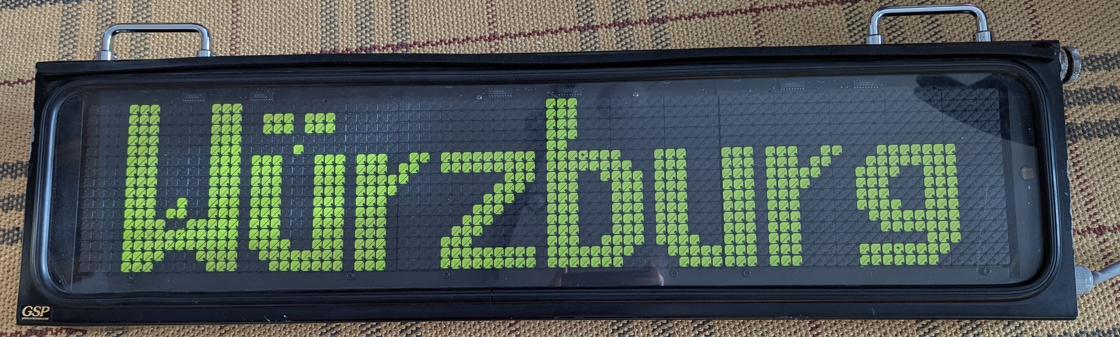
As previously said, the display is a combined LED/flipdot-display, to improve legibility in darkness. The board uses an ambient light sensor for two purposes. First, if the display is in bright sunlight, the LEDs are turned off completely: the LEDs are neither required (the flipdot pixels are well visible) nor useful (the LEDs would have to be very bright to even be visible). Second, it controls the brightness of the LEDs: they need to be brighter in sunset, but can be darker in the middle of the night to avoid dazzling.
I originally planned for this to be just a short section in this part of the series, but it turned out to be a much bigger and more complicated project than I originally anticipated :) so the ambient light sensor is discussed in the third part of the series!